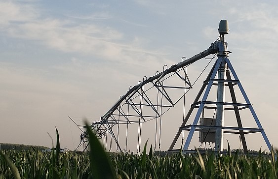
Electrical principle of circular sprinkler irrigation machine
Friends who are familiar with pointer type sprinkler irrigation machines know that the operation of the equipment starts with the last span, then drives the second to last span, and finally drives the third span Similarly, but you may not truly understand its operating principle. Today I will explain to you how electrical components make the sprinkler rotate.
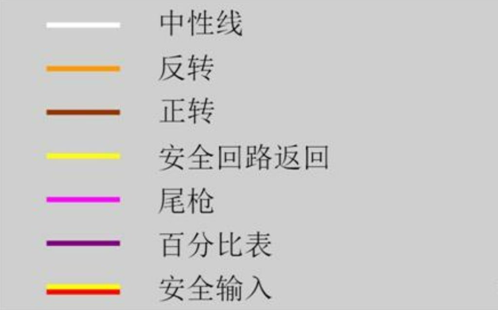
Firstly, let me show you the functions of each cable in the sprinkler control circuit.
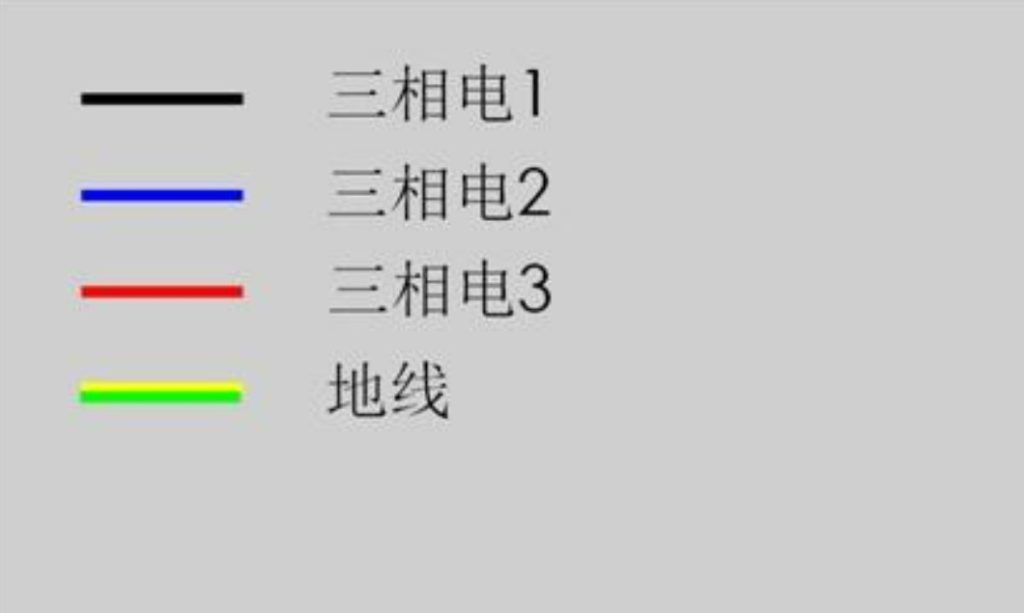
The power lines of sprinkler irrigation machines are as follows:
1. Collector ring
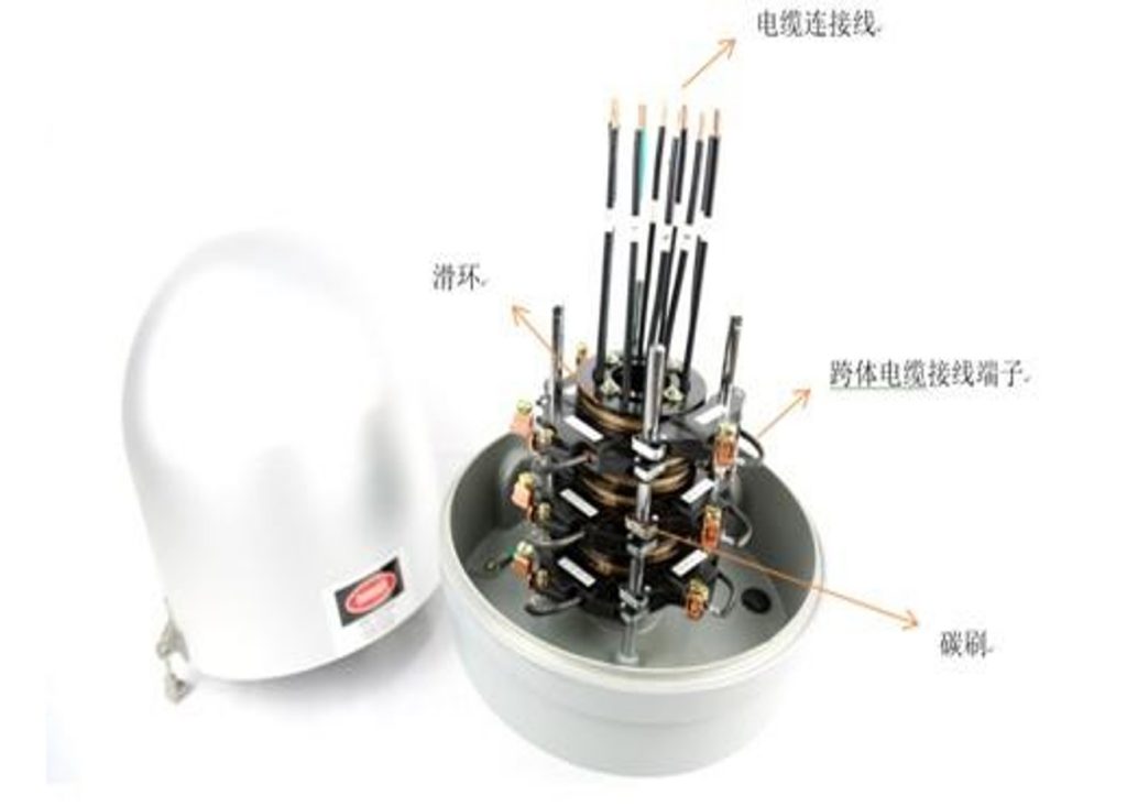
The center point of the pointer sprinkler is fixed and the cross body rotates around the center point. Without a collector ring, the cross body cable will inevitably become tangled, ultimately causing the equipment to fail to operate. The collector ring is actually a fixed slip ring, with carbon brushes on the outer layer. The central shaft is installed above the center point of the sprinkler system. When the equipment is running, the central slip ring and the center point remain stationary, while the outer carbon brushes move around the slip ring. The cable is connected to the slip ring wire through the central hole, and the cross body cable is connected to the carbon brush terminal, so that the slip ring can continuously supply power to the equipment.
2. Tower Box
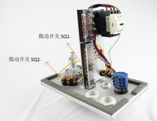
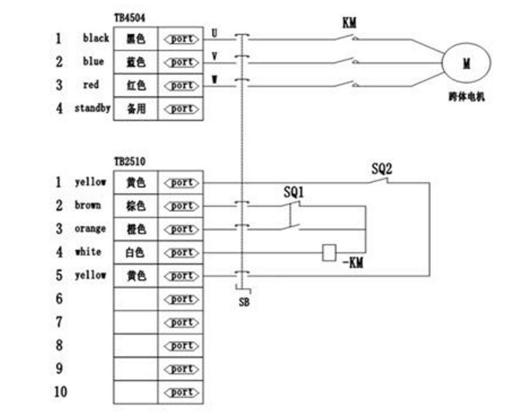
The pointer machine moves from the last span to drive the guide rod of the second to last span, creating an angle between the second to last span and the first to last span. It is located in the middle tower box above the second to last span, and touches the travel switch SQ1 inside the tower box through the guide device. SQ1 controls the driving motor to move by controlling the contactor KM, and so on until a straight line is maintained between the spans. The micro switch is disconnected, and the spans stop moving. The direction of the equipment’s movement is determined by the orange and brown lines output from the electrical control cabinet, as shown in the figure. In addition, when the equipment malfunctions and the cross body angle is too large, it will touch the safety micro switch SQ2, causing the safety circuit to disconnect and the equipment to stop for protection.
3. As mentioned earlier, the end tower box always starts from the last span and is installed above the equipment’s tail span to control the movement of the last span.
When the electric control cabinet sends out a walking signal, the end tower box responds first by controlling the contactor to control the walking motor of the last span, thereby driving the entire span to move. The end tower box does not control the direction of the walking motor, and the reverse direction is controlled by the electric control cabinet through controlling the phase sequence.
4. Terminal booster pump tower box
When installing a tail gun on a sprinkler irrigation machine, a booster pump is usually installed for boosting. Due to the fact that the sprinkler irrigation machine only has three cross body power lines, the booster pump needs to share this power supply with the cross body motor. However, when the sprinkler irrigation machine needs to switch between forward and reverse operation, changing the phase sequence of the power supply will be adjusted. If the booster pump motor is not adjusted accordingly, it will inevitably cause the booster pump to reverse, resulting in insufficient water pressure and long-term operation causing booster pump failure. Therefore, in the presence of a booster pump, we replace the end tower box with a booster pump tower box, which has the function of adjusting phase sequence and automatically opening and closing according to water pressure.
The power enters from the terminal and passes through the cross body operation contactor KM, which then outputs to control the cross body motor M.
Connect the power line to the booster pump motor protector GV2 at the upper end of the contactor KM, and connect the GV2 output line to the positive and negative contactors KM1 and KM2 of the booster pump. Connect the KM1 and KM2 output lines to the booster pump motor
The purple line is the percentage meter signal line. After entering terminal 11, it is directly connected to the KM coil of the cross body motor contactor through the power switch SB to control the movement of the cross body motor. The orange line is the reverse signal line, which is connected to relay KA after entering terminal 8. The closing and releasing of relay KA determines which of the booster pump contactors KM1 and KM2 is activated. The pink line for starting the booster pump enters from terminal 12 and passes through the power switch SB before being connected to the pressure switch. The outlet of the pressure switch is connected to the relay KA normally open and normally closed points, and then connected to the contactors KM1 and KM2 after the KA normally open and normally closed points come out. That is to say, the orange line determines the forward and reverse rotation of the booster pump, while the pink line determines when the booster pump runs. The pink line is connected in series with the pressure switch, and the booster pump only starts when the pressure is reached.